Arduino: "C/C++" Computing Science 10 (CS 10) and Computing Science 20 (CS 20)
Arduino Microcontrollers
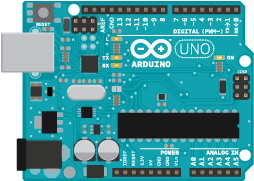
A microcontroller is a small computer containing a core processor, memory and programmable input and output ports that allow students to control LED's, motors, switches and servos in projects that they build using code that they program. The Arduino Uno shown below is one of the most accessible microcontrollers on the market today. With a little programming experience, it won't be long before you start interacting with the world around you in a completely new way!
A microcontroller is a small computer containing a core processor, memory and programmable input and output ports that allow students to control LED's, motors, switches and servos in projects that they build using code that they program. The Arduino Uno shown below is one of the most accessible microcontrollers on the market today. With a little programming experience, it won't be long before you start interacting with the world around you in a completely new way!
Programming with Arduino is incredibly similar to programming with Processing. To interface with an Arduino micro-controller, you will need to install the Arduino IDE.
|
Processing 3 IDE Window
Control Buttons Across Top:
|

|
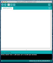
Arduino IDE Window
Control Buttons Across Top:
|
|
Like Processing, Arduino is also an open source and maker platform where people openly share what they learn and create. It is a developmental model promoting universal access via a free licence to the Arduino's design and any subsequent improvements. Examples of code are available for just about anything you can imagine and range from the simple "Blink" (the Arduino equivalent of "Hello World") to code that run motors and controls servos, to access and save information in numerous different formats or devices, to access information and data from sensors plugged into a microcontroller on your desktop or a sensor connected to the internet from anywhere around the world.
Some of the Formative and Summative Assignments to be covered during computing science 10:
- Modify the Blink or Fade code to simulate a "Heartbeat" and a "Warning Light."
- Create a replica of emergency flashing "Police Lights"
- Create a "Traffic Light" simulator for the lights at an intersection.
- Demonstrate serial communication between the Arduino and computer.
- Demonstrate understanding of Pulse Width Modulation (PWM) by displaying 5 LED's at differing levels of brightness.
- Build a "Larson Scanner" and then modify it to become a "Bargraph" display.
- Use "push button" control to switch the state of a program (incorporates the use of "debouncing" code) .
- Use a push button and an RGB LED to display 7 different colours with a single LED.
- Use a push button and a "7-Segment Display" to cycle through the digits 0 to 9.
- Control a motor incorporating the use of a "transistor" and a "push button."
- Manually control a motor incorporating the use of a "transistor" and a "potentiometer."
- Use serial communication to measure distance with an ultrasonic sensor.
- Create a bar graph or numeric distance meter using an ultrasonic sensor.
- Use serial communication to read infrared (IR) signals.
- Use infrared (IR) signals to control Arduino functions.
- Control two motors using a dual H-bridge controller.
- Build a remote controlled car.
- Build and code an autonomous car.
- Demonstrate reading data from a rotary encoder.
- Demonstrate understanding of Pulse Width Modulation (PWM) by controlling a servo motor via a rotary encoder.
- Build a Pan-Tilt servo assembly controlled by a mini-joystick.
- Build and use servo motors to control a robotic hand.
- Use concepts and knowledge learned to complete an individual project of the student's own choice.
Key Concepts and Proper Technique
Input/Output (I/O) Pins
There are fourteen digital (0 to 13) pins and 6 analog (A0 to A5) pins located along the edges of the Arduino microcontroller board. Each of these pins allow you to interface with something in the real world. Each pin can be assigned as either input to bring information into the Arduino or output to send information from the Arduino.
Initializing I/O Pins
To use any pin for input or output, you simply identify the pin in the program and state if will be used for input or output.
ex. If we want to use a pin to turn a LED on or off then we would need the following two lines of code in our program
first, we would identify a variable for what we're using and choose a pin to use
int LED = 13; //creates and assigns a variable for the LED
then we need to active the pin to control the LED
pinMode(LED, OUTPUT); //activates pin 13 (i.e. LED = 13) to sets it to output data
ex. If we want to control the three different LED's in a RGB LED then we would need to assign three pins
int RedLED = 11; //creates an assigns a variable for the red LED
int GreenLED = 12; //creates an assigns a variable for the green LED
int BlueLED = 13; //creates an assigns a variable for the blue LED
pinMode(RedLED, OUTPUT); //activates pin 11 to control the red LED
pinMode(GreenLED, OUTPUT); //activates pin 12 to control the green LED
pinMode(BlueLED, OUTPUT); //activates pin 11 to control the blue LED
Digital vs Analog
Data can generally be broken into two different groups: discrete data or continuous data. Computers can work with either group but approaches each group differently. Discrete data is identified as digital information while continuous data is known as analog (or analogue) information.

Here's an example to help you understand the difference [between digital and analog]. Consider a switch that controls a light in a room, if the switch is a simple on/off switch then the light will either be completely on or completely off, if however the switch is a dimmer switch then the light could be completely on, completely off or set to any light level between the two from very dim to very bright. The on/off switch is an example of a digital situation while the dimmer switch would be an example of an analog situation. Here is a good tutorial explaining the difference between analog and digital.
The most commonly used analog applications are reading and inputing information from the real world. If you create a weather station that measures the temperature then you would use an analog input. Here is what the code used in the program could look like:
int tempSensor = A0; //creates and assigns a variable for the temperature sensor
int tempValue = 0; //creates a variable to store the temperature sensor data
tempValue = analogRead(tempSensor); //reads the data from the temperature sensor
Driving LED's
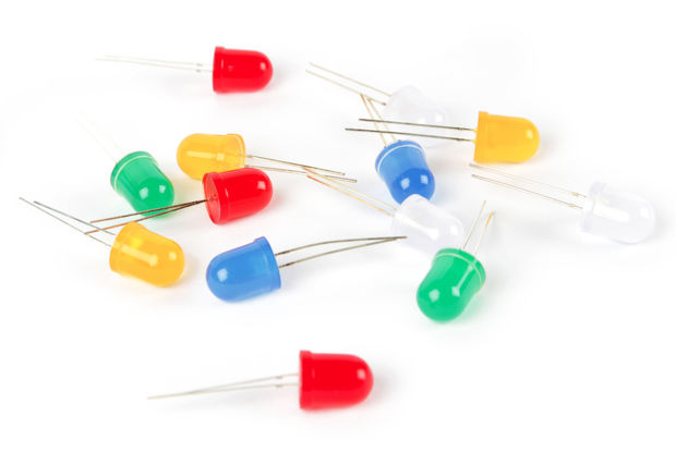
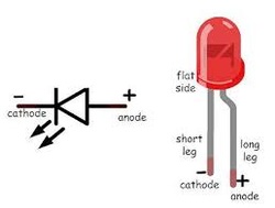
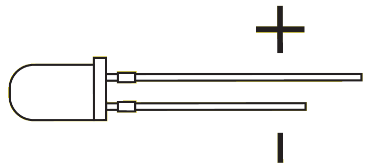
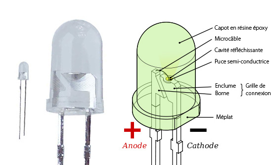
LED is the acronym for a Light Emitting Diode which is a basic electronic components. First off, a diode is a polarized electronic component that only allows an electric current to flow in one direction. LED's are a special type of diode that also emit light when an electric current flows through it. As a polarized component, if the LED doesn't light up then it may be reversed and simply needs to be switched around in order to work correctly. Basic LED's have two metal wires (known as "leads") that are connected to a power source (typically about 2 volts) to create a circuit. In the middle diagrams below, you can see that one of the LED's leads is longer than the other. The longer lead is called the "anode" and is connected to a positive power source while the shorter lead is called the "cathode" which is connected to the negative side of a circuit commonly referred to as the "ground." In digital circuits the ground (or negative side of a circuit) actually refers to the point in the circuit that equals zero volts.
The most commonly used analog applications are reading and inputing information from the real world. If you create a weather station that measures the temperature then you would use an analog input. Here is what the code used in the program could look like:
int tempSensor = A0; //creates and assigns a variable for the temperature sensor
int tempValue = 0; //creates a variable to store the temperature sensor data
tempValue = analogRead(tempSensor); //reads the data from the temperature sensor
Driving LED's
LED is the acronym for a Light Emitting Diode which is a basic electronic components. First off, a diode is a polarized electronic component that only allows an electric current to flow in one direction. LED's are a special type of diode that also emit light when an electric current flows through it. As a polarized component, if the LED doesn't light up then it may be reversed and simply needs to be switched around in order to work correctly. Basic LED's have two metal wires (known as "leads") that are connected to a power source (typically about 2 volts) to create a circuit. In the middle diagrams below, you can see that one of the LED's leads is longer than the other. The longer lead is called the "anode" and is connected to a positive power source while the shorter lead is called the "cathode" which is connected to the negative side of a circuit commonly referred to as the "ground." In digital circuits the ground (or negative side of a circuit) actually refers to the point in the circuit that equals zero volts.
|
|
|
|
Although you can drive an LED directly from a digital pin and the ground on the Arduino microcontroller, it is not recommended as you can damage the LED (and possibly the Arduino) depending upon what you're attempting to accomplish. Typical LED's require about 2 volts (2V) at a maximum current of 20 to 30 milli-amps (20 mA or 30 mA). Remember that "milli" means 1/1000 so 20 mA would be equivalent to 0.02 A. We can use a basic law of electronics called Ohm's Law (named after German physicist Georg Ohm) that relates voltage (V) in volts, electric current (A) in amps and resistance (Ω) in Ohm's: V = IR for this circuit. Note that the unit of resistance is a ratio of volts/amps called an Ohm (Ω). Here is a good tutorial for using Ohm's Law.
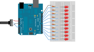
Arduino's are designed with a standard five volt positive output (+ 5V) on each of its digital pins. If LED's have a 2V voltage drop, then to safely light a LED we need to account for the remaining 3V (the difference of 5V from an Arduino less 2V for a LED). Using Ohm's Law: V = IR, we can enter these two values to determine the needed resistance to safely light a LED. V = IR becomes (3V) = (0.02 A)(R). Rewriting our equation to solve for resistance, R = (3V) / (0.02 A) which gives us a value of 150 V/A or more commonly written as 150 Ω's. To be extra safe, it's a fairly common practice to reduce the potentially damaging current travelling through LED's by further increasing the resistance. For example, if we wanted to reduce the current in half, simply double the resistance on the LED (i.e. 150 Ω's would become 300 Ω's). A readily available and cost effective choice is the 330 Ω's resistor as electronic supply companies tend to sell them in bulk.
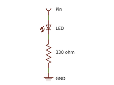
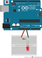
Here is the schematic diagram for wiring a LED and some images to show how to connect a LED (or multiple LED's) to an Arduino mircocontroller.
Arduino's are designed with a standard five volt positive output (+ 5V) on each of its digital pins. If LED's have a 2V voltage drop, then to safely light a LED we need to account for the remaining 3V (the difference of 5V from an Arduino less 2V for a LED). Using Ohm's Law: V = IR, we can enter these two values to determine the needed resistance to safely light a LED. V = IR becomes (3V) = (0.02 A)(R). Rewriting our equation to solve for resistance, R = (3V) / (0.02 A) which gives us a value of 150 V/A or more commonly written as 150 Ω's. To be extra safe, it's a fairly common practice to reduce the potentially damaging current travelling through LED's by further increasing the resistance. For example, if we wanted to reduce the current in half, simply double the resistance on the LED (i.e. 150 Ω's would become 300 Ω's). A readily available and cost effective choice is the 330 Ω's resistor as electronic supply companies tend to sell them in bulk.
Here is the schematic diagram for wiring a LED and some images to show how to connect a LED (or multiple LED's) to an Arduino mircocontroller.
|
|
|
Pulse Width Modulation
A digital circuit has only two states, it can either be on or off. That means that the digital output on an Arduino can either be +5V or 0V and nothing in between. So questions like "How do I dim a light?" or "How can I change the speed of a motor?" require a different approach than simply changing the voltage like you would with a wall dimmer switch. The answer is simple..., if you need half the voltage then simply turn on the voltage for half the time! This is the idea behind Pulse Width Modulation (PWM). By varying the ratio of the amount of time a digital pin is turned on relative to the time it's turned off will effectively change the effective output of the digital signal. Note, the time that the digital pin is turned on plus the time that the digital pin is turned off is called the "period" and represents how long it takes for one complete digital cycle or "duty cycle."
A digital circuit has only two states, it can either be on or off. That means that the digital output on an Arduino can either be +5V or 0V and nothing in between. So questions like "How do I dim a light?" or "How can I change the speed of a motor?" require a different approach than simply changing the voltage like you would with a wall dimmer switch. The answer is simple..., if you need half the voltage then simply turn on the voltage for half the time! This is the idea behind Pulse Width Modulation (PWM). By varying the ratio of the amount of time a digital pin is turned on relative to the time it's turned off will effectively change the effective output of the digital signal. Note, the time that the digital pin is turned on plus the time that the digital pin is turned off is called the "period" and represents how long it takes for one complete digital cycle or "duty cycle."
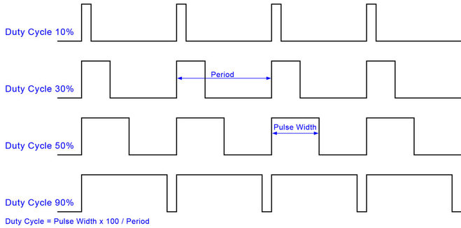
The duty cycle on an Arduino is 256, that is you can break the duty cycle of an Arduino into 256 units expressed as 0 to 255. Although we'll be using a digital pin, we use the analogWrite function to vary the pulse width. Consider the following examples:
To make an LED fade in brightness, simply turn on the LED for part of the duty cycle. If we request a duty cycle of 50% by using analogWrite(127) then we will be turning the LED on and off very quickly. Although the LED would be completely on for 50% of the time and completely off for the other 50%, our mind will trick us as we won't be able to see the LED flashing on and off so quickly and hence the LED appears to be dimmed to 50% of its full brightness.
Here is the basic code "Fade" required to repeatedly dim and brighten an LED on an Arduino:
/*
Fade
This example shows how to fade an LED on pin 9
using the analogWrite() function.
This example code is in the public domain.
*/
int led = 9; // the pin that the LED is attached to
int brightness = 0; // how bright the LED is
int fadeAmount = 5; // how many points to fade the LED by
// the setup routine runs once when you press reset:
void setup() {
// declare pin 9 to be an output:
pinMode(led, OUTPUT);
}
// the loop routine runs over and over again forever:
void loop() {
// set the brightness of pin 9:
analogWrite(led, brightness);
// change the brightness for next time through the loop:
brightness = brightness + fadeAmount;
// reverse the direction of the fading at the ends of the fade:
if (brightness == 0 || brightness == 255) {
fadeAmount = -fadeAmount ;
}
// wait for 30 milliseconds to see the dimming effect
delay(30);
}
- analogWrite(255) creates a 100% on duty cycle
- analogWrite(0) creates a 0% on duty cycle
- analogWrite(127) creates a duty cycle that's on 50% of the time
- analogWrite(63) creates a duty cycle that's on 25% of the time
- analogWrite(191) creates a duty cycle that's on 75% of the time
To make an LED fade in brightness, simply turn on the LED for part of the duty cycle. If we request a duty cycle of 50% by using analogWrite(127) then we will be turning the LED on and off very quickly. Although the LED would be completely on for 50% of the time and completely off for the other 50%, our mind will trick us as we won't be able to see the LED flashing on and off so quickly and hence the LED appears to be dimmed to 50% of its full brightness.
Here is the basic code "Fade" required to repeatedly dim and brighten an LED on an Arduino:
/*
Fade
This example shows how to fade an LED on pin 9
using the analogWrite() function.
This example code is in the public domain.
*/
int led = 9; // the pin that the LED is attached to
int brightness = 0; // how bright the LED is
int fadeAmount = 5; // how many points to fade the LED by
// the setup routine runs once when you press reset:
void setup() {
// declare pin 9 to be an output:
pinMode(led, OUTPUT);
}
// the loop routine runs over and over again forever:
void loop() {
// set the brightness of pin 9:
analogWrite(led, brightness);
// change the brightness for next time through the loop:
brightness = brightness + fadeAmount;
// reverse the direction of the fading at the ends of the fade:
if (brightness == 0 || brightness == 255) {
fadeAmount = -fadeAmount ;
}
// wait for 30 milliseconds to see the dimming effect
delay(30);
}
Debouncing Switches
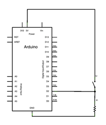
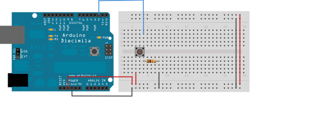
Using a physical switch, like a push button, to enter information into an Arduino can be problematic as at the actual physics of making a contact and closing a circuit in a switch can take longer than the speed that the Arduino runs at. When you close a switch or open a switch, you're changing whether electric current flows or not. The effect occurs because of something called "contact potential" and creates is a slight delay due to the inertia of electrons travelling from one side of the switch to the other. If we close a switch there will be slight delay in current following by brief surge just before the current levels off. We call this delay and small surge "switch bounce." The delay is very small and imperceptible to us but unfortunately it's very noticeable to an Arduino. The solution to this phenomena is to simply read the state of the switch once and then read it again after a short delay (5 milliseconds works great) and compare the two values. If the two values are the same then that is the true reading of your switch value.
This is how you properly connect a switch for an Arduino.
|
|
To use a pushbutton, you need to have the following code that debounces the input. It appears in three pieces in your program:
In the constants area, create a variable for the Arduino pin to be used for the pushbutton input and also create two Boolean variables (on/off, true/false, high/low,...) to compare when the pushbutton is pressed.
const
int BUTTON = 2; //Sets Button on Pin 2
boolean lastButton = LOW; //Last Button State
boolean currentButton = LOW; //Current Button State
Second assign the Arduino pin to accept for input in the void setup() section of the program
pinMode (BUTTON, INPUT); //Set Button as input
Then add the following Debouncing Code after the void setup() section and before the void loop(). The Debouncing Code is a complete function or module just like the void setup() and void loop().
boolean debounce(boolean last)
{
boolean current = digitalRead(BUTTON); //Read the Button state
if (last != current) //if it's different...
{
delay(5); //wait 5ms
current = digitalRead(BUTTON); //read the Button again
}
return current; //return the current value
}

Running Motors
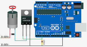
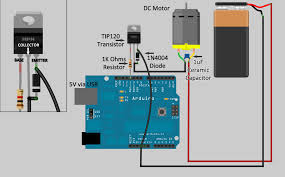
Safety Note: Running a standard motor without a "noise filter" will damage your Arduino. To safely use a motor, simply solder a capacitor (something like a 0.1 micro Farad ceramic capacitor) across the motor contacts, the capacitor will absorb the back current produced by the electro-motive force (EMF) as the motor turns. It's a simple but incredibly important fix!
Use a transistor (a basic NPN is perfect) to control a motor. A transistor, in it's simplest form is just an amplifier that allows you to put a lot more power through a motor than you can get from the Arduino but that the output powering the motor is directly proportional to the output from the Arduino.
|
|
|
H-Bridges
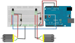
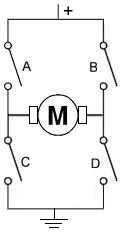
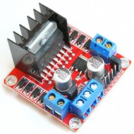
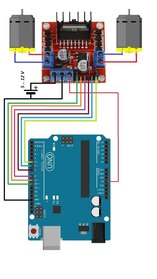
An "H-bridge" controller is a simple electronic circuit containing four transistors to control a single motor allowing it to rotate in a forward direction and a reverse direction. The name "H-bridge" comes from the shape of the circuit shown below left. A common version of a "H-bridge" controller used by many Arduino hobbyists and students is the Dual H-bridge controller L298N shown below centre. It's called a dual controller because it allows the control of two motors. The typical wiring for the L298N to control a robotic car is shown below right.
An "H-bridge" controller is a simple electronic circuit containing four transistors to control a single motor allowing it to rotate in a forward direction and a reverse direction. The name "H-bridge" comes from the shape of the circuit shown below left. A common version of a "H-bridge" controller used by many Arduino hobbyists and students is the Dual H-bridge controller L298N shown below centre. It's called a dual controller because it allows the control of two motors. The typical wiring for the L298N to control a robotic car is shown below right.
|
|
|
Stepper Motors
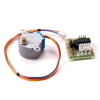
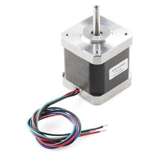
A "stepper motor" is a class of motors that has its full rotation broken into several discrete portions or steps. A stepper motor can be commanded to rotate an exact amount or number of times. Stepper motors are one of many common motors used in Arduino projects and used specifically if you need to keep track of the exact number of rotations to control your project.
A "stepper motor" is a class of motors that has its full rotation broken into several discrete portions or steps. A stepper motor can be commanded to rotate an exact amount or number of times. Stepper motors are one of many common motors used in Arduino projects and used specifically if you need to keep track of the exact number of rotations to control your project.
|
|
Controlling Servos
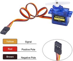
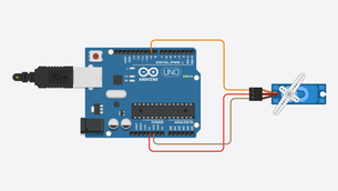
Unlike the stepper motors above, the servo motor is a specialized motor that contains a potentiometer (a.k.a. variable resistor) allowing for the precise measurement of position or rotational speed. Servo motors vary from the common small SG90 9G Micro Servo Motor shown bottom left to the more robust Hitech HS422 shown in the middle below, all servos regardless work the same way. Servo motors have a power lead (usually +5V), a ground and a control lead that reads a signal (usually Pulse Width Modulated or PWM).
Unlike the stepper motors above, the servo motor is a specialized motor that contains a potentiometer (a.k.a. variable resistor) allowing for the precise measurement of position or rotational speed. Servo motors vary from the common small SG90 9G Micro Servo Motor shown bottom left to the more robust Hitech HS422 shown in the middle below, all servos regardless work the same way. Servo motors have a power lead (usually +5V), a ground and a control lead that reads a signal (usually Pulse Width Modulated or PWM).
|

|
|
Here are some additional resources to help you get started.
Select any of the links below to check out the following microprocessor platforms and electronics suppliers.


Recommended Device: Laptops work best
